- 您现在的位置:买卖IC网 > Sheet目录3893 > PIC16F723A-I/SS (Microchip Technology)MCU PIC 7KB FLASH XLP 28-SSOP
2010-2012 Microchip Technology Inc.
DS41417B-page 205
PIC16(L)F722A/723A
Power-down Base Current (IPD)(2)
D027
—
0.06
0.7
5.0
A
1.8
A/D Current (Note 1, Note 4), no
conversion in progress
—
0.08
1.0
5.5
A3.0
D027
—
6
10.7
18
A
1.8
A/D Current (Note 1, Note 4), no
conversion in progress
—
7
10.6
20
A
3.0
—
7.2
11.9
22
A
5.0
D027A
—
250
400
—
A
1.8
A/D Current (Note 1, Note 4),
conversion in progress
—
250
400
—
A3.0
D027A
—
280
430
—
A
1.8
A/D Current (Note 1, Note 4,
Note 5), conversion in progress
—
280
430
—
A
3.0
—
280
430
—
A
5.0
D028
—
2.2
3.2
14.4
A
1.8
Cap Sense Low Power
Oscillator mode
—3.3
4.4
15.6
A3.0
D028
—
6.5
13
21
A
1.8
Cap Sense Low Power
Oscillator mode
—
8
14
23
A
3.0
—
8
14
25
A
5.0
D028A
—
4.2
6
17
A
1.8
Cap Sense Medium Power
Oscillator mode
—6
7
18
A3.0
D028A
—
8.5
15.5
23
A
1.8
Cap Sense Medium Power
Oscillator mode
—
11
17
24
A
3.0
—
11
18
27
A
5.0
D028B
—
12
14
25
A
1.8
Cap Sense High Power
Oscillator mode
—32
35
44
A3.0
D028B
—
16
20
31
A
1.8
Cap Sense High Power
Oscillator mode
—
36
41
50
A
3.0
—
42
49
58
A
5.0
23.3
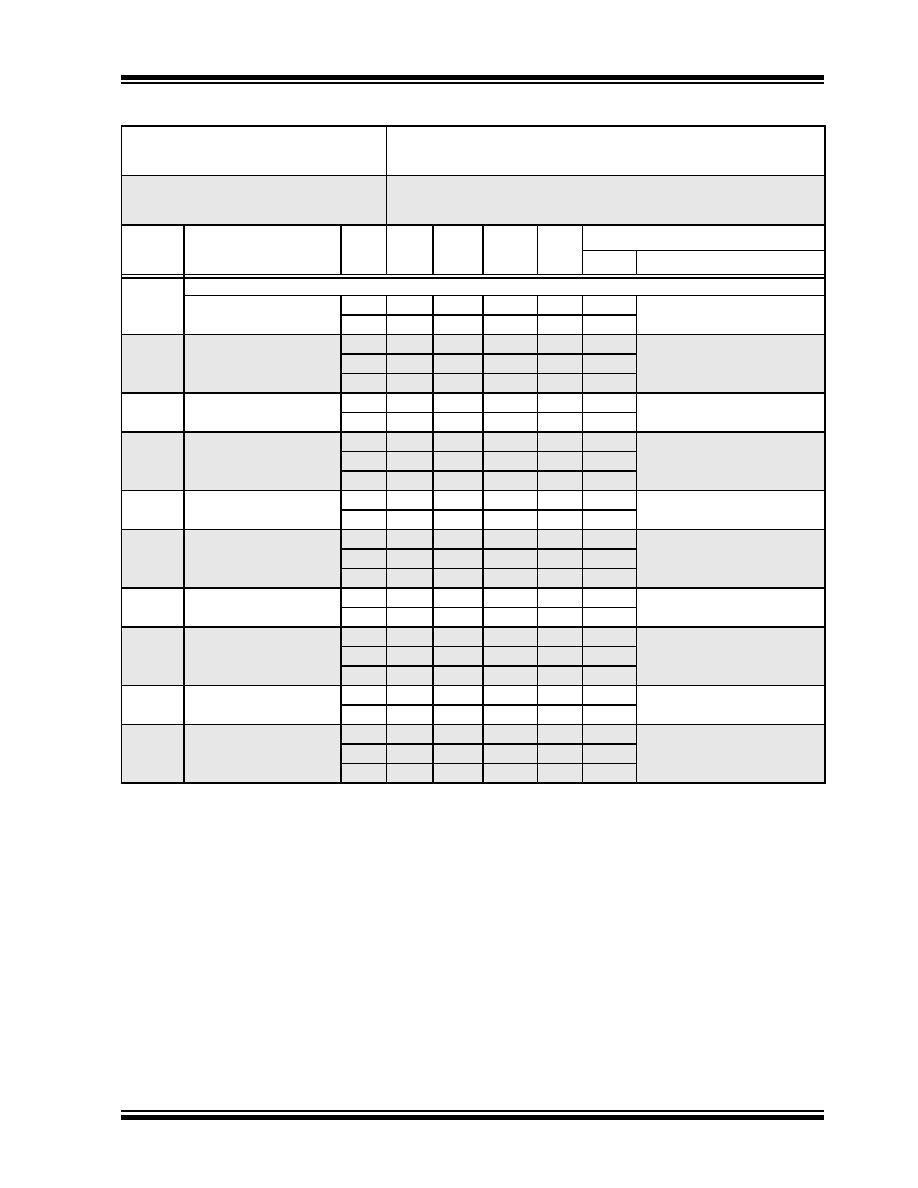
DC Characteristics: PIC16(L)F722A/723A-I/E (Power-Down) (Continued)
PIC16LF722A/723A
Standard Operating Conditions (unless otherwise stated)
Operating temperature
-40°C
TA +85°C for industrial
-40°C
TA +125°C for extended
PIC16F722A/723A
Standard Operating Conditions (unless otherwise stated)
Operating temperature
-40°C
TA +85°C for industrial
-40°C
TA +125°C for extended
Param
No.
Device Characteristics
Min.
Typ
Max.
+85°C
Max.
+125°C
Units
Conditions
VDD
Note
Data in “Typ” column is at 3.0V, 25°C unless otherwise stated. These parameters are for design guidance only and are
not tested.
Note 1:
The peripheral current is the sum of the base IDD or IPD and the additional current consumed when this peripheral is
enabled. The peripheral
current can be determined by subtracting the base IDD or IPD current from this limit. Max
values should be used when calculating total current consumption.
2:
The power-down current in Sleep mode does not depend on the oscillator type. Power-down current is measured with
the part in Sleep mode, with all I/O pins in high-impedance state and tied to VDD.
3:
Fixed Voltage Reference is automatically enabled whenever the BOR is enabled.
4:
A/D oscillator source is FRC.
5:
0.1
F capacitor on VCAP (RA0).
发布紧急采购,3分钟左右您将得到回复。
相关PDF资料
PIC12C508A-04/SN
IC MCU OTP 512X12 8SOIC
PIC12C509A-04/SM
IC MCU OTP 1KX12 8-SOIJ
PIC16LF627T-04I/SO
IC MCU FLASH 1KX14 COMP 18SOIC
PIC12C509A-04/P
IC MCU OTP 1KX12 8DIP
PIC18LC452T-I/PT
IC MCU OTP 16KX16 A/D 44TQFP
PIC12LF1822-I/MF
IC MCU 8BIT FLASH 8DFN
PIC12F1822-I/P
IC MCU 8BIT FLASH 8PDIP
PIC12F1822-I/MF
IC MCU 8BIT FLASH 8DFN
相关代理商/技术参数
PIC16F723AT-I/ML
功能描述:8位微控制器 -MCU 7KB Flash 1.8V-5.5V. 16 MHz int Osc RoHS:否 制造商:Silicon Labs 核心:8051 处理器系列:C8051F39x 数据总线宽度:8 bit 最大时钟频率:50 MHz 程序存储器大小:16 KB 数据 RAM 大小:1 KB 片上 ADC:Yes 工作电源电压:1.8 V to 3.6 V 工作温度范围:- 40 C to + 105 C 封装 / 箱体:QFN-20 安装风格:SMD/SMT
PIC16F723AT-I/MV
功能描述:8位微控制器 -MCU 7KB Flash 1.8V-5.5V. 16 MHz int Osc RoHS:否 制造商:Silicon Labs 核心:8051 处理器系列:C8051F39x 数据总线宽度:8 bit 最大时钟频率:50 MHz 程序存储器大小:16 KB 数据 RAM 大小:1 KB 片上 ADC:Yes 工作电源电压:1.8 V to 3.6 V 工作温度范围:- 40 C to + 105 C 封装 / 箱体:QFN-20 安装风格:SMD/SMT
PIC16F723AT-I/SO
功能描述:8位微控制器 -MCU 7KB Flash 1.8V-5.5V. 16 MHz int Osc RoHS:否 制造商:Silicon Labs 核心:8051 处理器系列:C8051F39x 数据总线宽度:8 bit 最大时钟频率:50 MHz 程序存储器大小:16 KB 数据 RAM 大小:1 KB 片上 ADC:Yes 工作电源电压:1.8 V to 3.6 V 工作温度范围:- 40 C to + 105 C 封装 / 箱体:QFN-20 安装风格:SMD/SMT
PIC16F723AT-I/SS
功能描述:8位微控制器 -MCU 7KB Flash 1.8V-5.5V. 16 MHz int Osc RoHS:否 制造商:Silicon Labs 核心:8051 处理器系列:C8051F39x 数据总线宽度:8 bit 最大时钟频率:50 MHz 程序存储器大小:16 KB 数据 RAM 大小:1 KB 片上 ADC:Yes 工作电源电压:1.8 V to 3.6 V 工作温度范围:- 40 C to + 105 C 封装 / 箱体:QFN-20 安装风格:SMD/SMT
PIC16F723-E/ML
功能描述:8位微控制器 -MCU 7 KB Flash 18V-55V 16 MHz Int Osc RoHS:否 制造商:Silicon Labs 核心:8051 处理器系列:C8051F39x 数据总线宽度:8 bit 最大时钟频率:50 MHz 程序存储器大小:16 KB 数据 RAM 大小:1 KB 片上 ADC:Yes 工作电源电压:1.8 V to 3.6 V 工作温度范围:- 40 C to + 105 C 封装 / 箱体:QFN-20 安装风格:SMD/SMT
PIC16F723-E/MV
功能描述:8位微控制器 -MCU 7KB Flash 1.8V-5.5V RoHS:否 制造商:Silicon Labs 核心:8051 处理器系列:C8051F39x 数据总线宽度:8 bit 最大时钟频率:50 MHz 程序存储器大小:16 KB 数据 RAM 大小:1 KB 片上 ADC:Yes 工作电源电压:1.8 V to 3.6 V 工作温度范围:- 40 C to + 105 C 封装 / 箱体:QFN-20 安装风格:SMD/SMT
PIC16F723-E/SO
功能描述:8位微控制器 -MCU 7 KB Flash 18V-55V 16 MHz Int Osc RoHS:否 制造商:Silicon Labs 核心:8051 处理器系列:C8051F39x 数据总线宽度:8 bit 最大时钟频率:50 MHz 程序存储器大小:16 KB 数据 RAM 大小:1 KB 片上 ADC:Yes 工作电源电压:1.8 V to 3.6 V 工作温度范围:- 40 C to + 105 C 封装 / 箱体:QFN-20 安装风格:SMD/SMT
PIC16F723-E/SP
功能描述:8位微控制器 -MCU 7 KB Flash 18V-55V 16 MHz Int Osc RoHS:否 制造商:Silicon Labs 核心:8051 处理器系列:C8051F39x 数据总线宽度:8 bit 最大时钟频率:50 MHz 程序存储器大小:16 KB 数据 RAM 大小:1 KB 片上 ADC:Yes 工作电源电压:1.8 V to 3.6 V 工作温度范围:- 40 C to + 105 C 封装 / 箱体:QFN-20 安装风格:SMD/SMT